Hi ,
When a shell-and-tube heat exchanger fails to achieve required duty during sizing, the quickest software reaction is to increase basic dimensions.
Enlarge the shell diameter. Extend the tube length. Add more tubes.
It solves the duty problem on paper, but it is the most expensive solution for your project in CAPEX, weight, and plot space.
Before changing dimensions, inspect the thermal resistance breakdown table:
1/U = (1/h_shell) + Rf_shell + R_wall + Rf_tube + (1/h_tube)
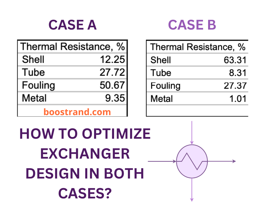
In many cases, the exchanger is held back by one controlling side:
1. Tube-Side Controlling (e.g., Tube Resistance > 25%, Shell < 15%):
The tube fluid is running too slowly. Increasing the pass count (from 2 to 4 or 6) halves the flow area and doubles velocity, significantly increasing the tube-side heat transfer coefficient. Always verify that the additional tube-side pressure drop does not exceed available pump head.
2. Shell-Side Controlling (e.g., Shell Resistance > 60%):
Optimizing tube passes here does nothing. You need to reduce baffle spacing or optimize baffle cut (typically 20% to 25% ID per TEMA) to increase cross-flow mass velocity. Watch out for flow-induced vibration limits.
Metal resistance is almost always negligible, so changing tube alloy won't salvage thermal performance.
We put together a full article detailing the thermal design aspects of shell-and-tube exchangers, including baffle arrangements, velocity limits, and pressure drop tradeoffs:
Read the complete breakdown here:
https://boostrand.com/understand-thermal-design-aspects-of-shell-tube-heat-exchangers/
If you want to master the complete modeling and optimization workflow inside HTRI:
https://boostrand.com/heat-exchangers
Keep designing safely,
Boostrand ChemE
P.S. When you see an underperforming exchanger, which resistance do you usually see dominating: shell, tube, or fouling? Just hit reply and let me know.
0 comments